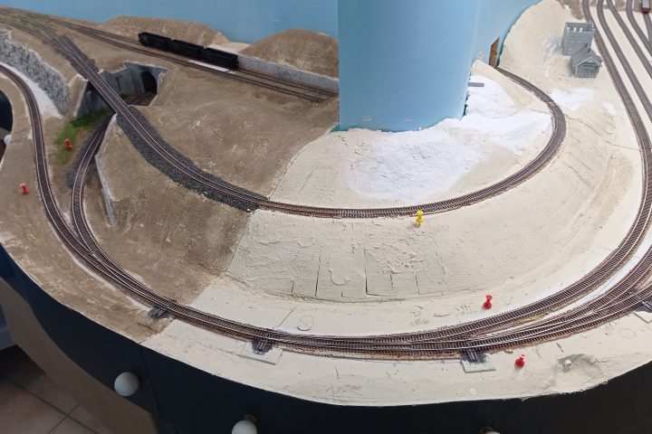
Here is part two for my endeavor into junction signaling at Bend Jct.
In addition to the planed signals to govern the turnout routes, I plan to add an occupancy detection for the turnouts. This idea occurred not only for the junction, but I had it in mind for a longer time. I didn’t want to go with the common current sensing, as I didn’t divide the power routes into dedicated sections. I had some kind of add-on system in mind, so I opted for some optical detection.
I choose the IR detection with tiny ITR8307 reflex sensors and wrote some lines of code for an ATtiny84 chip to calculate the detection and block/junction occupation. As I have four entry-/exit points to the junction, I need a logic that marks the junction as occupied while triggering one of the sensors. Occupation is removed after one of the remaining three sensors detects the end of the train. This is calculated by releasing a sensor after it is triggered.
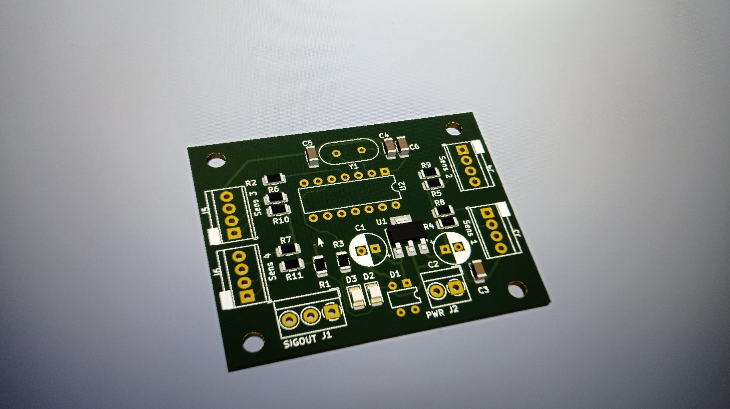
With the named IR sensors and the ATtiny I built a test circuit on a breadboard and took some measurements for resistor-values to adjust the sensitivity of the sensors. After all was satisfying, I went on and draw a PCB and got it etched. To keep it small, I choose some SMD parts.
I added a status LED to the board as well as two lines to guide the occupation signal to the signal-driver boards.
In a revision of the PCB I will omit the external crystal as running the ATtiny on its internal 1MHz clock of is more than fast enought to compute the code.
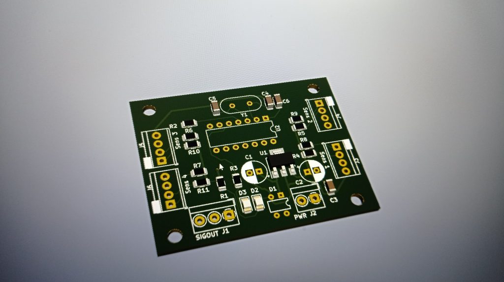
3D render of the PCB 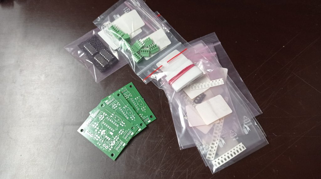
The PCB and the parts arrived …. 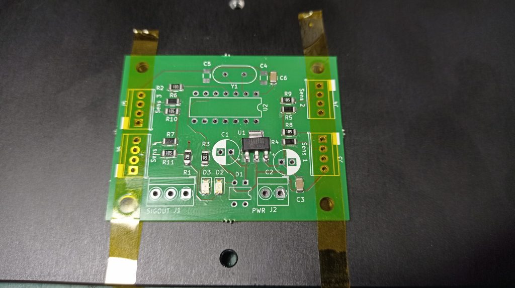
hot air soldering of the SMD parts 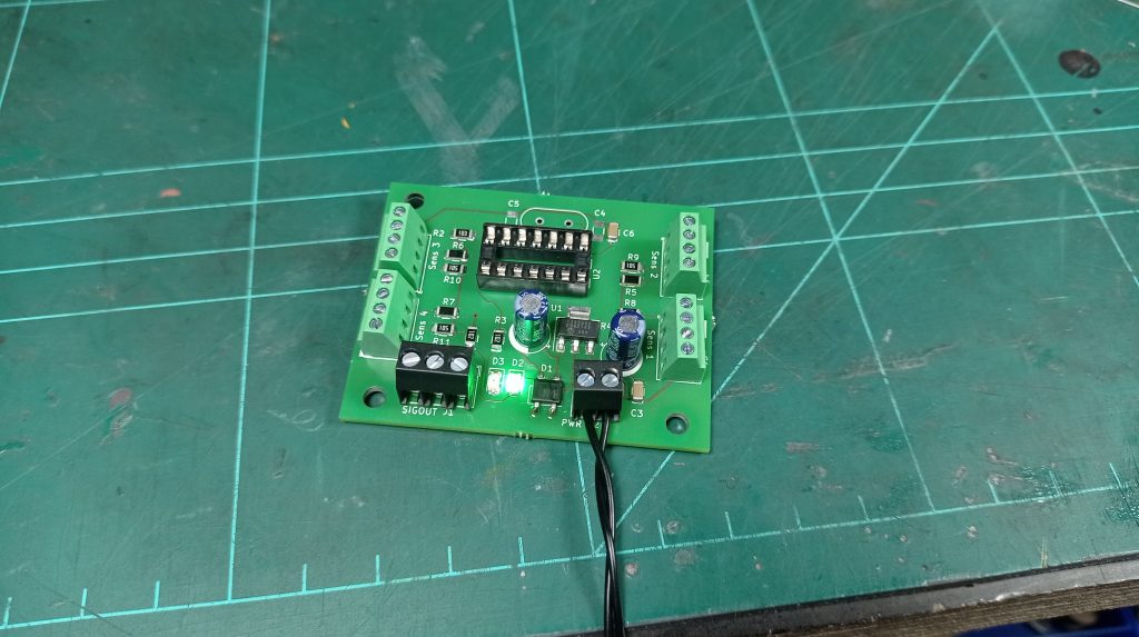
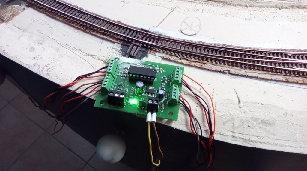
power applied, green light, seems to work.
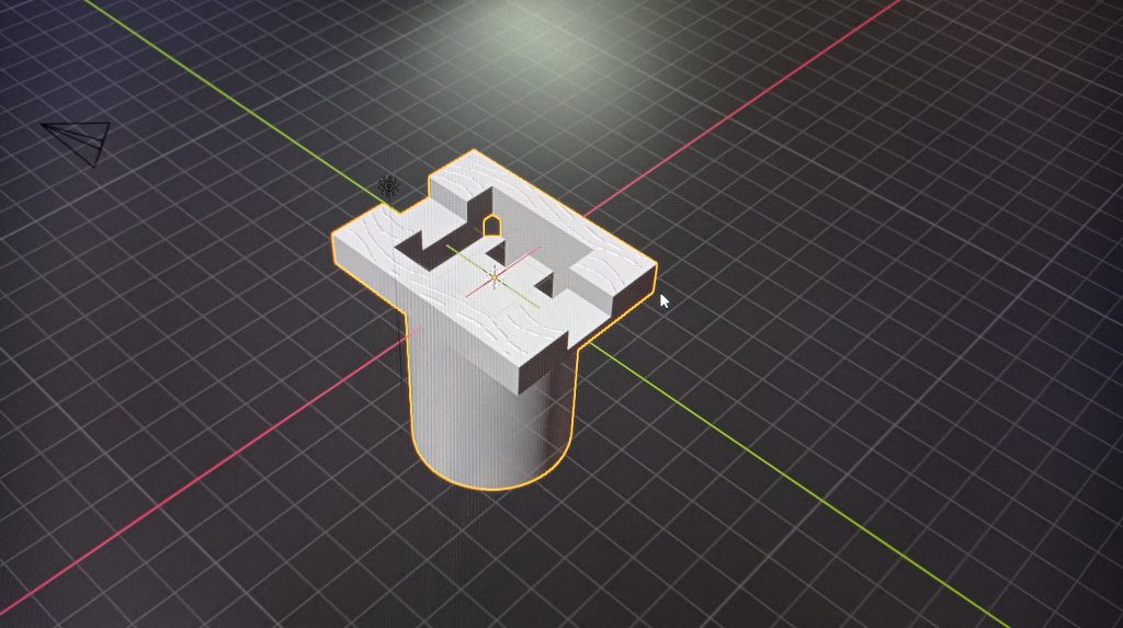
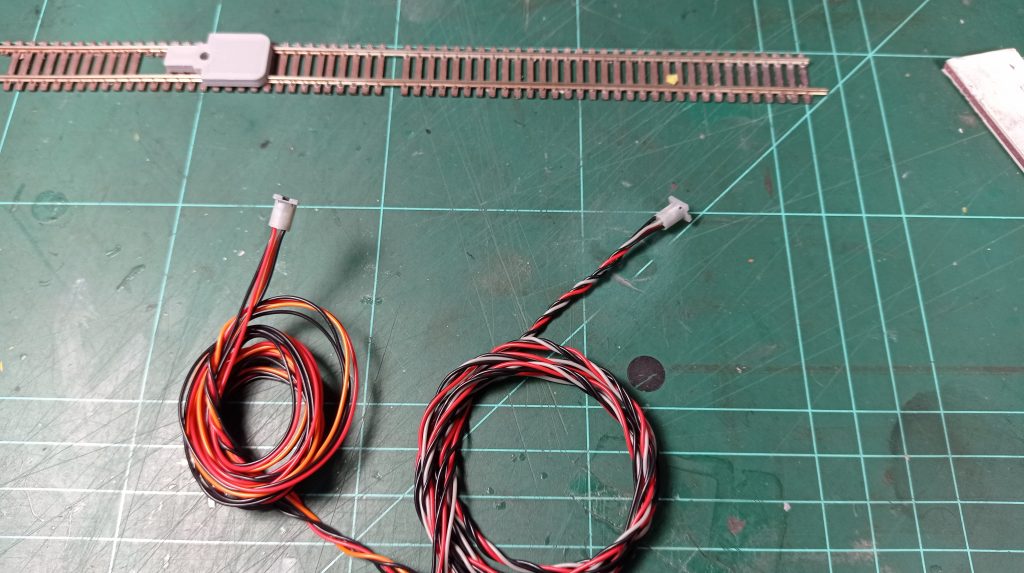
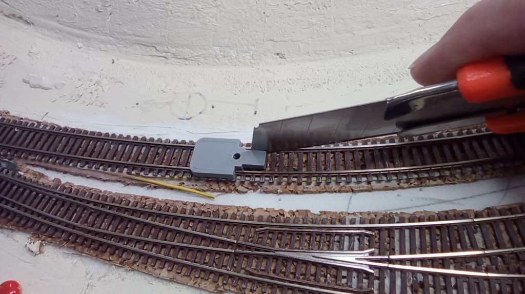
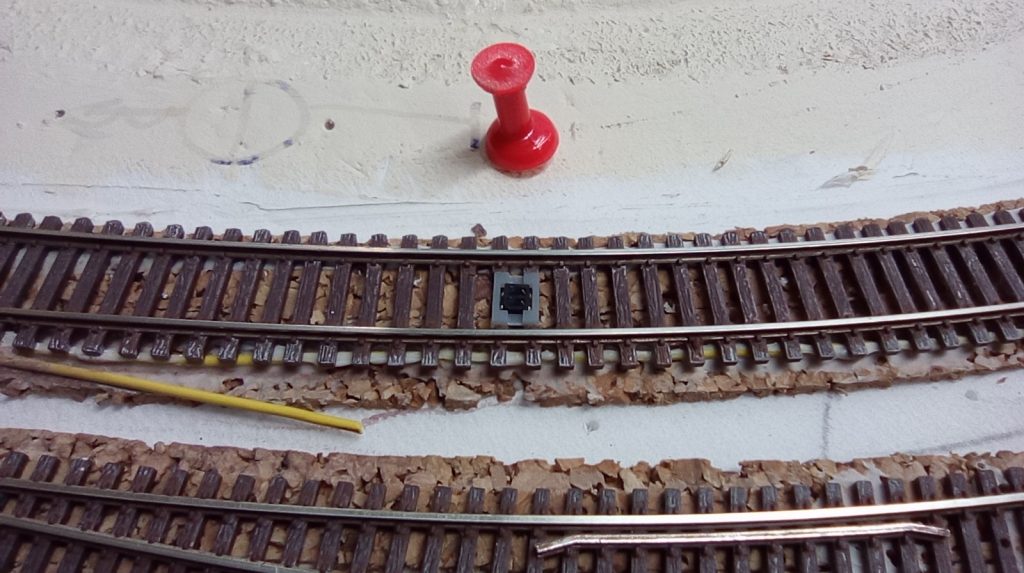
As the ITR8307 are 7mm wide, they fit between the rails of the ATLAS Code 55 track and stretch over two ties. I designed a housing to fit the tie spacing and holding the ITR in place.
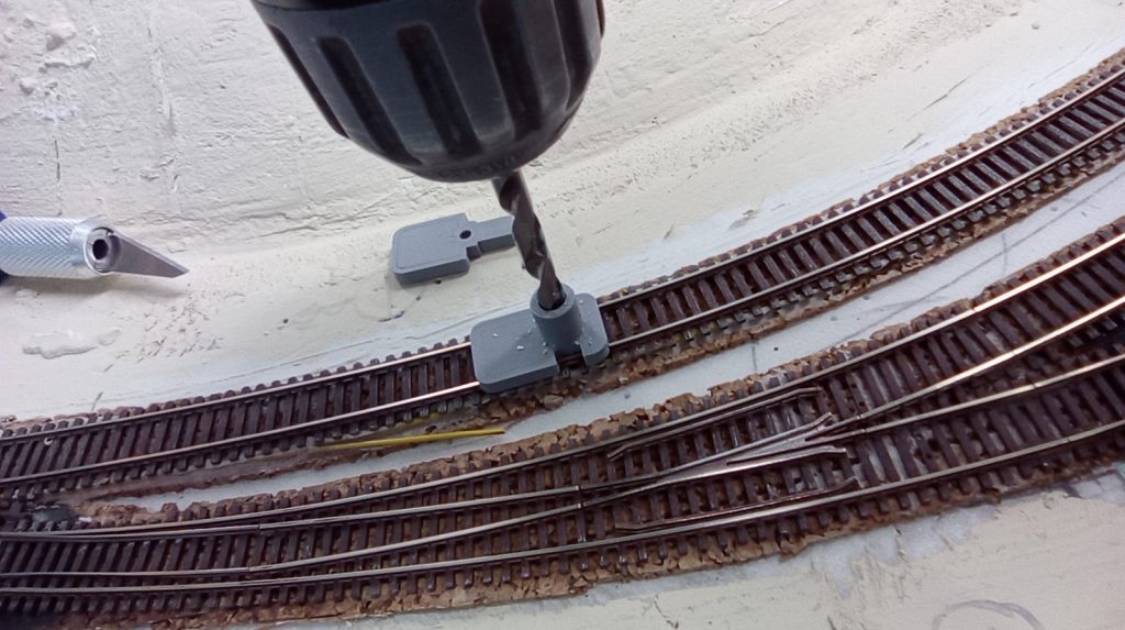
To get the right position on the track and for a drill guide I designed a template that snaps on the rails and helps mark the ties I need to remove and guides the drill-bit square to the track.
The a closeup of the sensor and the finished controler board are shown below.
I recorded a short video showing the work of the detection. https://youtu.be/ogM59lo57uc
